
TotalJoist is an innovative and efficient cold-formed-steel floor joist that offers a robust, simplified framing solution compared to traditional wood or structural steel joists.
Installed similarly to wood joists but with far more strength and ease of use, TotalJoist has been named the most accommodating joist in the industry.
TotalJoist comes with more benefits than you ever thought possible. It provides a vibration-controlled floor with simplified fire ratings and allows for larger spans while eliminating bulkheads. Architects also love TotalJoist’s ability to dramatically increase design options by allowing unprecedented clear spans that create larger, open space rooms with higher strength.
This article illustrates the many options you have with TotalJoist, and how the steel joist can be used with many structural elements, including wood framing, steel framing, masonry and ICF.
A Selection of Popular TotalJoist Design Configurations

BASIC SYSTEM ASSEMBLY, A-1.1
This diagram shows a series of TotalJoist with a layout for the resilient channel on the bottom (to hold gypsum or drywall for ceiling installation) and T&G plywood over top. Note the end connectors, which can be easily drilled into walls.

UL M511 / ULC M520 ASSEMBLY, A-1.2(A)
This design shows the basic system assembly with 3 ½ AFB batt insulation. This solution provides a one-hour fire-resistance rating in accordance with UL M511 / ULC M520.

UL M515 / ULC M521 ASSEMBLY, A-1.2(B)
This option showcases the UL M511 design with the addition of 8” TotalJoist bridging.
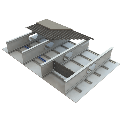
ASSEMBLY WITH STEEL DECK AND CONCRETE TOPPING, A-1.5
This drawing is a TotalJoist assembly with the blocking, steel TotalDecking and a layer of concrete.
TOTALJOIST® BLOCKING, A-3.2A
This blocking diagram shows how rim board blocking and TotalJoist Blocking are added to the assembly.

TOTALJOIST® SOLID BLOCKING, A-3.2B
This drawing illustrates the TotalJoist and solid blocking panel assemblies.

JOIST LABELING FOR HOLE ALIGNMENT, A-3.4
This drawing shows how the labels on your TotalJoist products will arrive and how they should be installed along the support line.

PLYWOOD SCREW INSTALLATION, A-3.5
This diagram shows the preferred installation if you use plywood flooring on your TotalJoist.

CEILING INSTALLATION, A-3.6
This ceiling drawing gives you a typical panel screw pattern and proven techniques to ensure your gypsum board is properly installed.

SUBFLOOR PREPARATION FOR CERAMIC TILE, A-3.7
Ceramic tiles require additional support and are shown in this diagram. Note the multiple layers of plywood, product spacing and fastener patterns.

STEEL DECK SCREW PATTERN, A-3.8
Installing steel decking should be done carefully and using the proper screw patterns. This should be specified by the design engineer. Place concrete uniformly over the deck so as not to overload the structure.

2-PLY JOIST CONSTRUCTION, A-3.9
Two joists can be fastened together to add strength to your structural system. This solution requires multi-ply connectors.

TOTALJOIST® WEB HOLE ALLOWANCE / SIZES, A-3.10
Large pre-punched service holes are designed into the TotalJoists allowing for HVAC and other utility services. This diagram showcases the sizing and placement options for these holes.

END CONNECTOR SCHEDULE, A-4.2
This adjustable piece connects to the end of TotalJoists to be connected to the wall structure.

MULTI-PLY Z CONNECTOR SCHEDULE, A-4.3

OVERLAP CONNECTOR SCHEDULE, A-4.7
This shows the sizing of the overlap connector for connecting joists with a depth of 9 ½” to 16”.

PLATFORM FRAMING, FOUNDATION LEVEL, B-1.1
This design shows how the TotalJoist is connected to the foundation wall’s sill plate.

PLATFORM FRAMING, 2ND STOREY AND ABOVE, B-1.2
This illustration shows how ceiling components are affixed to the underside of TotalJoist in conjunction to load-bearing walls for 2nd storey and above.

PLATFORM FRAMING, SIDE, B-1.3
This drawing shows how TotalJoist works with the rim board blocking and rim board.

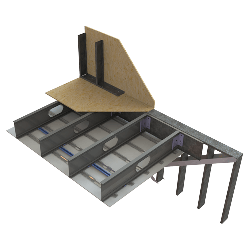
STAIRWAY OPENING, B-1.4
TotalJoist works with a wide range of openings, including stairway openings, that allow for easy installation of stringers.

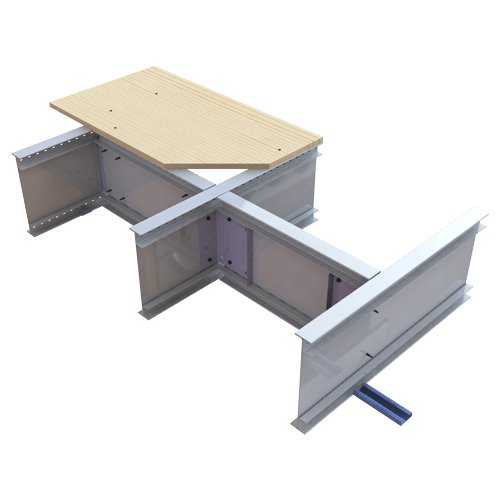
JOISTS OVERLAPPED OVER INTERIOR SUPPORT, B-1.5
Connect two TotalJoists with the overlap connector, as illustrated in this drawing.

2-PLY PLATFORM FRAMING CONNECTION, B-1.6
This drawing shows how two-ply joist construction connects to rim boards.

JOISTS CONTINUOUS OVER INTERIOR SUPPORT, B-1.7A
You can use full-height end connectors when installing TotalJoists over interior supports.

JOISTS CONTINUOUS OVER INTERIOR SUPPORT, B-1.7B
This drawing has joists continuous over interior supports with the addition of blocking when required.

STRINGER CONNECTION, B-1.8
This is a detailed drawing showing how a stringer should be connected to the rim board (which can be fastened to TotalJoist).

STARTER JOIST USING RIM BOARD, B-1.9(A)
In some applications, a rim board is required to be used as a starter joist. This drawing shows how the board should be connected to the wall and TotalJoist.

STARTER JOIST USING LADDER BLOCKING, B-1.9(B)
In some applications, ladder blocking is required to be used as a starter joist. This drawing shows how the ladder blocking should be connected to the wall and TotalJoist.

CANTILEVER PARALLEL TO JOIST SPAN, B-1.10
TotalJoists can be extended to support balconies, decks and enclosed spaces. This drawing illustrates how this can be done.
JOIST CONNECTION TO STEEL STUD WALL, B-2.2
This drawing shows the connection from a TotalJoist to a steel-stud wall.

JOIST PARALLEL TO STEEL STUD WALL, B-2.4(B)
Steel stud walls can be easily connected to plywood and TotalJoist with this diagram.

2-PLY TO 2-PLY JOIST CONNECTION, B-2.6
Two-ply TotalJoists must be connected to other structural joists with two sets of connectors.

CANTILEVER PARALLEL TO SPAN, B-2.10
This drawing shows how to fasten end connectors to the track sections of a cantilever system.

CANTILEVER PERPENDICULAR TO SPAN, B-2.11
The layout in this drawing is required when cantilevers are perpendicular to the floor joists.

JOIST CONTINUOUS OVER STRUCTURAL STEEL BEAM, B-3.1(A)
TotalJoist can span over structural steel beams using a wood nailer plate illustrated here.

CONNECTION TO STRUCTURAL STEEL BEAM, B-3.1(B)
This connection layout is required for TotalJoists that end atop a structural steel beam.

JOIST TO STRUCTURAL STEEL BEAM, WELDED HANGER, B-3.2(A)
Connectors and welded hangers are required for TotalJoists which end at structural steel beams.

JOIST TO STRUCTURAL STEEL BEAM, NAILED HANGER, B-3.2(B)
For TotalJoists which end at structural steel beams, and when welded hangers are not an option, use wood nailers as illustrated in this drawing.

JOISTS OVERLAPPED OVER STRUCTURAL STEEL BEAM, B-3.3
Overlap connectors are used to connect TotalJoists which are toe-screwed to sill plates.

JOIST CONTINUOUS OVER STRUCTURAL STEEL BEAM, B-3.4(A)
This design illustrates how continuous TotalJoists connect to wood nailer plates over structural steel beams.

2-PLY JOIST TO STRUCTURAL STEEL BEAM CONNECTION, B-3.4(B)
This design illustrates how two-ply TotalJoists connect to wood nailer plates over structural steel beams.

2-PLY TO STRUCTURAL STEEL BEAM, WELDED HANGER, B-3.5(A)
This design illustrates how two-ply TotalJoists connect to multi-ply hangers welded to structural steel beams.

2-PLY TO STRUCTURAL STEEL BEAM, NAILED HANGER, B-3.5(B)
This design illustrates how two-ply TotalJoists connect to multi-ply hangers that are screwed into wood nailers affixed to structural steel beams.

JOIST END CONNECTION TO CMU WALL, B-4.1(B)
This drawing shows TotalJoist connections directly into concrete masonry units (CMUs) using structural steel angle.
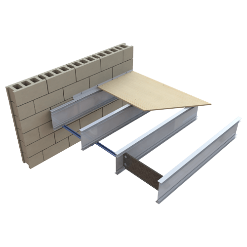
SIDE PLYWOOD SUPPORT, B-4.2
This drawing shows TotalJoists running parallel to concrete masonry units (CMUs). Connections are possible using structural steel angle and plywood flooring support.

SIDE DECK SUPPORT, B-4.3
This drawing shows TotalJoists running parallel to concrete masonry units (CMUs). Connections are possible using structural steel angle and a concrete/steel deck.

2-PLY END CONNECTION TO MASONRY WALL, B-4.5
This drawing shows two-ply TotalJoist connections with concrete masonry units (CMUs), steel angle and a concrete/steel deck.

JOIST END CONNECTION, ICFVL CONNECTOR, B-5.1(A)
This drawing shows two-ply TotalJoist connections with concrete masonry units (CMUs), steel angle and plywood.

JOIST END CONNECTION, ICFVL CONNECTOR, B-5.1(A)
TotalJoist easily connects to ICF walls using a steel ledger track and ICFVL connectors shown in this drawing.

SIDE PLYWOOD SUPPORT, B-5.2
When TotalJoists run parallel to ICF walls, make connections using TotalJoist, steel angle and plywood.

SIDE DECK SUPPORT, B-5.3
When TotalJoists run parallel to ICF walls, make connections using TotalJoist, steel angle and a steel/concrete flooring system.
Where Can I Take My Design Next?
Reach out to our team to learn more about how TotalJoist can connect with your materials and alleviate construction concerns. We ship across North America!

